Ok, lets start:)
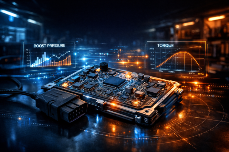
Modern ECU tuning often looks deceptively simple from the outside. You plug a device into the OBD port, click a few buttons, wait a few minutes, and suddenly the vehicle behaves completely differently. More power, sharper throttle response, revised torque limits — all delivered through what appears to be a routine diagnostic connector under the dashboard.
But behind that simplicity lies a highly controlled engineering process designed by the vehicle manufacturer. Writing a file through OBD is not just “uploading a tune.” It is a coordinated interaction between specialized software, vehicle networks, embedded security systems, and the microcontroller inside the ECU itself. Every step — from establishing communication to erasing flash memory and verifying data integrity — is governed by strict protocols to prevent corruption, tampering, or failure.
For professional tuners, understanding what actually happens during an OBD flash is more than curiosity. It explains why some ECUs can be programmed easily while others require bench access, why voltage stability is critical, why security access exists, and why a failed write can render a module unresponsive. It also clarifies the difference between legitimate programming operations and the advanced techniques used when factory protections block direct access.
This article breaks down the process from the inside out. Starting the moment a tuning tool is connected to the OBD port, we will follow the chain of events that leads all the way to the ECU’s flash memory being erased, rewritten, and validated. The goal is not just to describe the procedure, but to reveal the architecture that makes it possible — the bootloaders, diagnostic sessions, security mechanisms, and memory management systems that operate behind the scenes every time a file is written.
Whether you are a professional tuner, a shop owner, or simply someone who wants to understand what your tools are actually doing, this deep dive will give you a clear picture of how OBD flashing really works inside the ECU.
What Happens When You Plug Into the OBD Port
When a tuning tool connects to a vehicle through the OBD port, it is not simply “reading the car.” What actually happens is a structured digital handshake between two computers: the tuning device and the ECU (Engine Control Unit). Modern vehicles are distributed networks of control modules, and the OBD connector is the official gateway into that network.
The OBD Port Is a Network Access Point — Not Just a Connector
The 16-pin OBD-II port gives access to the vehicle’s communication buses. Depending on the car, this may include:
- CAN (Controller Area Network) — most modern vehicles
- K-Line (ISO 9141 / KWP2000) — older vehicles
- Sometimes multiple CAN buses routed through a gateway module
When you plug in a device like Autotuner, KESS3, CMD, or any professional flasher, the tool powers up using pin 16 (battery +12V) and ground pins 4/5. Immediately after power is established, the device begins scanning the communication lines to determine which protocol the vehicle is using.
In many modern cars, the OBD port does not connect directly to the engine ECU. Instead, it connects to a central gateway module that controls which requests are allowed to pass through to the drivetrain network. This is why some vehicles require ignition on, door closed, or even security unlocking procedures before programming can begin.
Establishing Communication With the Vehicle Network
Once powered, the tool sends diagnostic “wake-up” messages across the bus. Think of this as knocking on the network door.
Typical sequence:
1. Tool broadcasts a request on the CAN bus
2. ECUs listening on that bus evaluate whether the message is addressed to them
3. The engine ECU responds if the request matches its diagnostic address
At this stage, the communication protocol matters. Most modern flashing uses UDS (Unified Diagnostic Services), while older systems may use KWP2000. These protocols define exactly how messages are formatted, how long responses can take, and how large data transfers are handled.
This is not generic communication — it is a tightly specified conversation defined by automotive standards.
Identifying the ECU and Its Capabilities
Before any reading or writing can occur, the tool must identify the control unit.
The flasher typically requests:
- ECU hardware number
- Software version
- Calibration ID
- VIN stored in the ECU
- Supported diagnostic services
This identification step is critical. It tells the tool:
* Which protocol variant to use
* Whether OBD programming is supported
* Memory layout expectations
* Security requirements
Professional tools maintain large databases mapping these identifiers to known programming strategies. That is why the same tool behaves differently on different vehicles even though the physical connection is identical.
Switching From Normal Operation to Diagnostic Mode
Under normal conditions, the ECU is busy running the engine: controlling fuel, ignition, torque, emissions systems, and safety checks. It will not allow memory operations while doing this.
So the next step is requesting a diagnostic session.
The tool asks the ECU to enter a mode where diagnostics have priority over engine control tasks. In this state:
- Certain background functions are reduced
- Communication timeouts change
- Memory services become available
This transition is tightly controlled because accidental entry into programming mode while driving would be catastrophic.
The Gateway Factor in Modern Vehicles
On newer platforms, especially from around 2018 onward, the gateway module plays a major role. Some vehicles implement Secure Gateway systems that block programming commands unless the tool authenticates itself or the gateway is unlocked.
This is why professional tools often include gateway bypass procedures or require physical access to the vehicle network beyond the OBD port.
Without gateway approval, programming requests may never reach the ECU at all.
Voltage Stability and Power Management
Before proceeding further, most professional tools check vehicle voltage. Flashing requires stable power because the ECU’s flash memory operations are extremely sensitive to voltage drops.
If battery voltage falls during a write operation:
- Memory sectors may be partially erased
- Firmware may become corrupted
- The ECU may fail to boot
This is why external power supplies are recommended during programming sessions.
This Point, Nothing Has Been Written Yet
Up to this stage, the tool has only:
- Powered itself from the vehicle
- Established communication
- Identified the ECU
- Entered a diagnostic session
No flash memory has been touched.
Only after these steps will the tool attempt to enter programming mode, request security access, and begin memory operations — which is where actual file writing starts.
This initial connection phase determines whether OBD flashing is even possible on that vehicle. If communication fails here, the process stops before any risk to the ECU exists.
Understanding this stage explains why professional tuning tools sometimes appear to “hang” at the beginning of a job. They are negotiating access to one of the most tightly controlled computers in the vehicle.
How the ECU Switches Into Programming Mode
Under normal conditions, the engine control unit is fully occupied with real-time tasks: calculating fuel injection, ignition timing, torque requests, emissions control, thermal protection, and dozens of safety strategies. In this state, the ECU will not allow any operation that could interfere with engine control — especially writing to flash memory. To safely reprogram the unit, the ECU must transition into a dedicated programming mode where memory operations take priority over everything else.
This transition does not happen automatically when a tool is plugged into the OBD port. It must be explicitly requested through the diagnostic protocol, and the ECU will only accept the request if a strict set of conditions is met.
Diagnostic Sessions: The Gateway to Programming
Modern ECUs implement multiple diagnostic sessions, each with different permission levels. In standard operation, the ECU runs in what is often called the default session, where only basic diagnostic functions are allowed — reading fault codes, viewing live data, and performing routine service operations.
To begin reprogramming, the tool sends a request for a higher-privilege session, typically called the programming session. This request is transmitted using the diagnostic protocol (usually UDS on CAN).
Internally, the ECU’s firmware evaluates the request and checks whether programming is allowed at that moment. Conditions may include:
- Ignition state
- Engine not running
- Vehicle speed zero
- Battery voltage within safe limits
- No critical faults present
If any of these conditions fail, the ECU rejects the request and remains in normal mode.
If accepted, the ECU transitions into programming session mode. This does not yet allow writing, but it unlocks access to the functions required for the next steps.
What Changes Inside the ECU
Switching sessions triggers significant changes in the ECU’s internal behavior.
Engine control tasks are minimized or suspended. Nonessential background processes are halted. Communication timeouts are extended to allow large data transfers. Memory protection rules are adjusted to permit flash operations.
In effect, the ECU shifts from being a real-time control computer to a device ready to receive new software.
On some platforms, torque monitoring and safety watchdogs are temporarily relaxed. This is why ignition must remain on and voltage stable — the ECU is operating outside its normal safety envelope during programming.
The Role of Security Access
Even in programming session, the ECU still protects its memory. Before any erase or write command is accepted, the tool must pass a security challenge known as seed-key authentication.
The ECU generates a numerical seed and sends it to the tool. The tool must calculate the correct key using a proprietary algorithm and return it. Only if the calculated key matches the ECU’s expectation will memory access be unlocked.
This mechanism ensures that only authorized service equipment — or tools that understand the algorithm — can modify the firmware.
Without successful security access, the ECU will remain in programming session but refuse all flash commands.
Preparing the Flash Memory System
Once security is granted, the ECU prepares its flash memory controller for programming operations. This preparation may include:
- Disabling interrupts that could corrupt memory writes
- Copying flash routines into RAM (since flash cannot be read while being erased)
- Unlocking specific memory sectors
- Adjusting watchdog timers
Running flash routines from RAM is particularly important. During erase and write operations, the flash array becomes temporarily unavailable for code execution, so the ECU must execute the programming algorithms from a different memory region.
Why This Process Exists
Manufacturers design this layered approach to prevent accidental or malicious corruption of critical software. Without session control and security authentication, any device connected to the OBD port could potentially overwrite engine firmware.
The programming mode acts as a controlled maintenance state — one that allows updates while preserving safety and reliability.
When Programming Mode Cannot Be Entered
If the ECU refuses to enter programming session, OBD flashing becomes impossible. Common reasons include:
- Tuning protection enabled
- Gateway blocking diagnostic requests
- Unsupported software version
- Locked security access
- Hardware conditions not met
In such cases, alternative methods like bench programming or boot mode access are required to bypass the normal operating firmware.
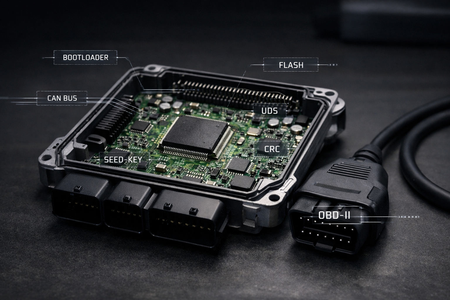
The Role of the Bootloader in ECU Reprogramming
At the center of every OBD flashing operation lies a small but critical piece of software inside the ECU: the bootloader. While the main application software controls the engine during normal operation, the bootloader is responsible for managing firmware updates, memory operations, and recovery procedures. Without it, safe reprogramming through the OBD port would not be possible.
What the Bootloader Actually Is
The bootloader is a dedicated program stored in a protected area of the ECU’s flash memory. It executes before the main application when the processor starts, and it contains the routines necessary to erase, write, and verify flash memory.
In simple terms, the bootloader is the ECU’s built-in firmware installer.
Unlike the main engine control software, it is designed to be stable, minimal, and difficult to corrupt. Manufacturers often protect this region so that it cannot be overwritten during normal programming. This ensures there is always a recovery mechanism available if the main software becomes damaged.
Why Flashing Cannot Be Done Directly by the Application
The main ECU software cannot safely rewrite itself while running from the same flash memory it needs to modify. Flash memory operations require sectors to be erased before new data can be written, and during erase operations the affected memory region becomes temporarily unavailable.
To solve this, the bootloader handles programming tasks using routines that execute from RAM or from protected memory areas. This separation prevents the ECU from erasing code that is currently in use.
How the Bootloader Takes Control
When the ECU enters programming mode, control is transferred to the bootloader’s programming routines. From this point onward, the bootloader becomes the component that:
- Receives data blocks from the diagnostic interface
- Erases specified flash sectors
- Writes incoming data to memory
- Verifies integrity after programming
- Manages resets after completion
The tuning tool communicates with these routines using standardized diagnostic services. The bootloader interprets those commands and performs the actual memory operations at the hardware level.
Memory Layout and Protected Regions
A typical ECU flash layout separates the bootloader from the application and calibration areas. This structure allows the main firmware to be replaced while leaving the programming capability intact.
Because the bootloader is essential for recovery, it is usually locked against modification through OBD programming. Only specialized factory procedures or low-level access methods can change it.
If the bootloader were accidentally erased, the ECU would lose its ability to accept new software through normal channels, often requiring hardware-level intervention to restore functionality.
Fail-Safe and Recovery Functions
Bootloaders also implement safety mechanisms designed to prevent permanent failure during interrupted programming. If power is lost or communication stops mid-write, the bootloader can detect incomplete programming during the next startup and remain in a state where reprogramming is still possible.
This is why many ECUs can recover from failed flashes through OBD, while others may require bench or boot mode access depending on how robust the bootloader implementation is.
The Difference Between Firmware and Bootloader Updates
Most tuning operations modify only the application and calibration data. The bootloader itself remains untouched. Updating the bootloader is considered a critical operation typically reserved for factory service procedures because an error at this level could remove all standard recovery options.
Why Understanding the Bootloader Matters for Tuners
For professional tuners, knowing the role of the bootloader explains several real-world scenarios:
- Why some ECUs allow OBD writing and others do not
- Why certain memory regions cannot be modified
- Why interrupted flashes sometimes remain recoverable
- Why bench or boot mode programming bypasses normal protections
It also clarifies that the tuning tool is not writing directly to flash memory on its own. Instead, it is instructing the ECU’s bootloader to perform those operations safely.
The bootloader is the hidden layer that makes controlled reprogramming possible. It bridges the gap between external diagnostic tools and the internal flash memory of the ECU, ensuring that new software can be installed without compromising the integrity of the system.
Understanding this component is essential to understanding how OBD flashing works as a whole, because every successful write operation ultimately depends on the bootloader executing its programming routines correctly.
Security Access: Seed-Key Authentication Explained
Once the ECU has entered programming mode, it still does not immediately allow memory operations. Before any erase or write command is accepted, the ECU requires proof that the device requesting access is authorized. This is enforced through a challenge-response mechanism known as Security Access, commonly referred to as seed-key authentication.
For professional tuners, this is one of the most critical — and least understood — parts of the flashing process. It is the barrier between simple diagnostic access and full control over the ECU’s firmware.
Why Security Access Exists
From the manufacturer’s perspective, the ECU contains safety-critical and emissions-regulated software. Allowing unrestricted access through the OBD port would expose the vehicle to tampering, accidental damage, or malicious modification.
Security Access ensures that only approved service equipment can:
- Enter programming mode fully
- Erase flash memory
- Write new firmware
- Modify calibration data
Without passing this authentication step, the ECU will ignore any commands that attempt to change its memory.
The Challenge-Response Process
Seed-key authentication works as a dynamic handshake between the ECU and the programming tool.
- The tool requests security access.
- The ECU generates a random or pseudo-random number called the seed.
- The seed is sent to the tool.
- The tool calculates a key using a proprietary algorithm.
- The calculated key is sent back to the ECU.
- The ECU verifies the key internally.
If the key matches what the ECU expects, access is granted. If not, the request is denied and additional attempts may be temporarily blocked.
Because the seed changes each time, the correct key must be calculated in real time. This prevents simple replay attacks or static passwords.
Security Levels and Permissions
Most ECUs implement multiple security levels, each unlocking different capabilities. Lower levels may allow limited diagnostics, while higher levels enable full programming functions.
For example:
- Level 1: Extended diagnostics
- Level 2: Calibration access
- Level 3: Full firmware programming
The tuning tool must request the correct level depending on the operation it intends to perform.
Where the Algorithm Lives
The seed-key algorithm is embedded inside the ECU firmware and is not publicly documented. Manufacturers treat it as proprietary intellectual property.
Professional tuning tools gain access to programming functions by implementing the correct algorithm for each ECU type. This is why tool compatibility varies by vehicle and software version — the authentication method may differ even between similar ECUs.
In newer platforms, this process may also involve cryptographic methods or hardware security modules inside the processor.
Protection Against Unauthorized Attempts
To prevent brute-force attacks, ECUs typically enforce lockout mechanisms. If incorrect keys are submitted repeatedly, the ECU may:
- Delay further attempts
- Require ignition cycling
- Reset the diagnostic session
- Temporarily disable programming access
Some systems escalate protection after multiple failures, making access increasingly difficult without proper authorization.
Why Security Access Matters in Real Tuning Work
Understanding seed-key authentication explains several situations encountered in practice:
- Why certain ECUs cannot be programmed via OBD
- Why updates sometimes break tool compatibility
- Why different tools support different vehicles
- Why programming may suddenly stop working after a software update
It also highlights the difference between legitimate programming operations and low-level methods that bypass factory protections.
Beyond Seed-Key: Modern Security Layers
In newer vehicles, seed-key authentication is only one layer. Additional protections may include:
- Digital signatures on firmware
- Secure boot verification
- Encrypted communication
- Gateway authentication
These systems are designed to ensure that even if programming access is granted, only approved software can be installed.
Security Access is the gatekeeper of ECU reprogramming. It separates basic diagnostic communication from the ability to modify the software that controls the engine.
Every successful OBD flash depends on passing this authentication step. Without it, the ECU will remain in programming session but refuse to alter its memory, regardless of the commands sent.
Understanding this mechanism provides a clear picture of why ECU programming is not simply data transfer, but a controlled process built on layered security designed to protect the integrity of the vehicle’s core systems.
Understanding ECU Memory Layout: Boot, Application, Calibration
Inside every modern ECU, the firmware is not stored as a single continuous block of code. Instead, the flash memory is carefully divided into functional regions, each with a specific role in how the control unit starts, operates, and can be reprogrammed. For tuners, understanding this memory layout explains why some areas can be modified safely via OBD while others are locked or inaccessible.
At a high level, most automotive ECUs organize their internal flash into three primary sections:
Bootloader, Application, and Calibration.
Bootloader Region — The Foundation
The bootloader occupies a protected area at the beginning of flash memory. This is the first code executed when the processor powers on. Its responsibilities include:
- Initializing hardware at startup
- Verifying software integrity
- Managing programming routines
- Providing recovery capability
Because it enables reprogramming, manufacturers protect this region heavily. Standard OBD flashing procedures typically cannot overwrite the bootloader. Only specialized factory tools or low-level access methods can modify it.
If this section were corrupted, the ECU could lose its ability to communicate or accept new software, which is why it is treated as critical infrastructure within the control unit.
Application Region — The Operating Software
The application area contains the main engine control software — the logic that actually runs the vehicle. This includes:
- Fuel injection control
- Ignition timing strategies
- Torque management
- Emissions systems
- Safety monitoring
- Diagnostic logic
When the ECU boots normally, control is passed from the bootloader to this application code.
Most factory software updates and full firmware flashes replace this section. Changes here alter how the ECU behaves at a fundamental level, not just performance parameters.
Because the application interacts directly with hardware in real time, programming this region carries higher risk than modifying calibration data. Errors can prevent the ECU from starting correctly.
Calibration Region — The Tuning Data
The calibration area contains the adjustable data tables and parameters used by the application software. This is where tuners primarily work.
Typical calibration content includes:
- Fuel maps
- Ignition maps
- Boost targets
- Torque limiters
- Throttle behavior
- Rev limits
- Temperature corrections
The application code reads these values during operation to determine how the engine should behave under different conditions.
Manufacturers separate calibration from application code so that updates can be made without rewriting the entire firmware. This separation also allows different vehicle variants to share the same base software while using different calibrations.
Most OBD tuning operations modify only this region, which is why they are generally safer and faster than full firmware programming.
Why the Separation Matters
This structured layout enables controlled updates and protects critical functions.
If calibration data becomes corrupted, the bootloader can still initiate recovery procedures. If the application fails, the bootloader may still allow reprogramming. Each layer provides a fallback for the others.
For tuners, this explains several real-world behaviors:
- Partial reads that include only calibration data
- Faster write times for map-only flashes
- Restrictions on full firmware access
- Differences between “virtual read” and full read operations
It also clarifies why some tools advertise calibration-only programming while others support full firmware flashing.
Memory Addressing and Sector Boundaries
Flash memory is divided into sectors or blocks that must be erased before new data can be written. Each region occupies specific address ranges within the processor’s memory map.
Programming operations must respect these boundaries. Attempting to erase a sector containing critical boot code, for example, could disable the ECU.
Professional tools therefore use predefined memory layouts tailored to each ECU type to ensure only the correct areas are modified.
How This Layout Enables Safe Reprogramming
By isolating essential functions from adjustable data, the ECU can support updates while minimizing the risk of permanent failure.
The bootloader ensures programming capability always exists. The application controls the engine. The calibration defines how the engine behaves.
Together, these regions form a layered architecture that balances flexibility, safety, and recoverability.
Understanding ECU memory layout transforms the flashing process from a black box into a structured operation. Instead of “writing a file,” the tuning tool is targeting specific memory regions designed for modification while leaving the core system intact.
This knowledge is especially valuable when diagnosing failed flashes, compatibility issues, or limitations encountered with different programming methods, because those outcomes are often determined by how the ECU’s memory is organized internally.
Checksums, CRC, and Why Verification Matters
After the new data has been written into the ECU’s flash memory, the job is not finished. Before the control unit will accept and run the updated software, it must confirm that the data stored in memory is exactly what was intended — byte for byte. This verification process relies on mathematical integrity checks known as checksums and CRC (Cyclic Redundancy Check).
For tuners, this stage is critical. A perfectly written calibration that fails verification can prevent the engine from starting, trigger fault codes, or force the ECU into a protective state.
Why Verification Exists
Flash memory programming is not guaranteed to be flawless. Electrical noise, voltage fluctuations, communication interruptions, or hardware limitations can introduce errors during data transfer or storage. Even a single incorrect bit can change how the software behaves.
Manufacturers therefore implement integrity checks to ensure that:
- The firmware was written correctly
- No data corruption occurred
- The software remains consistent with expected parameters
- The ECU can safely execute the code
Without verification, the ECU would risk running damaged software, which could lead to unpredictable engine behavior or safety issues.
What a Checksum Is
A checksum is a calculated value derived from a block of data. The ECU computes this value using a predefined algorithm and compares it to a stored reference value.
If the calculated checksum matches the expected one, the data is assumed to be intact.
If it does not match, the ECU detects an error and may refuse to operate normally.
Checksums are commonly used to validate calibration areas, ensuring that map data has not been altered incorrectly or corrupted.
What CRC Adds
CRC is a more advanced and reliable form of checksum designed to detect a wider range of errors. It can identify patterns of corruption that simpler checksum methods might miss.
CRCs are often applied to:
- Entire firmware images
- Critical application sections
- Communication packets during flashing
Because CRC algorithms are more robust, they are widely used in modern ECUs to guarantee software integrity.
Verification During the Flash Process
Integrity checks occur at multiple stages:
- During data transfer — ensuring each block arrives correctly
- After writing to flash — confirming memory contents match the transmitted data
- During startup — validating that stored software is safe to execute
Some ECUs compute verification values internally after programming and report the result to the flashing tool. Others require the tool to calculate and update the checksum before writing.
Why Tuners Must Correct Checksums
When calibration data is modified, the original checksum becomes invalid because the data has changed. If the checksum is not recalculated and updated, the ECU will detect a mismatch.
Possible outcomes include:
- No engine start
- Fault codes related to software integrity
- Limp mode operation
- Immediate shutdown after ignition
Professional tuning tools automatically correct checksums before writing modified files, ensuring the ECU accepts the new data as valid.
Modern Integrity Protections
Newer ECUs may implement additional verification layers beyond traditional checksums and CRCs, such as:
- Digital signatures
- Secure boot validation
- Runtime integrity monitoring
These mechanisms ensure not only that the data is intact, but also that it originates from an approved source.
Why This Matters in Real-World Flashing
Verification explains several scenarios encountered in tuning work:
- Why a modified file may cause a no-start condition
- Why tools spend time verifying after writing
- Why voltage stability is essential during programming
- Why corrupted reads can produce unusable files
It also clarifies why experienced tuners treat checksum handling as a fundamental requirement rather than a minor detail.
Checksums and CRC verification are the ECU’s final safeguard before accepting new software. They ensure that what was written into memory is complete, accurate, and safe to run.
Understanding this process highlights that ECU programming is not just about transferring data, but about maintaining the integrity of a complex embedded system where even the smallest error can have significant consequences.
Why Some ECUs Cannot Be Written via OBD
While OBD flashing has become the standard method for ECU tuning, not every control unit allows programming through the diagnostic port. In practice, tuners frequently encounter vehicles where reading may be possible but writing is blocked — or where even identification fails. These limitations are not random; they are the result of deliberate architectural and security decisions made by manufacturers.
Understanding why some ECUs cannot be written via OBD clarifies when bench programming, boot mode access, or ECU removal becomes necessary.
Factory Programming Restrictions
Not all ECUs are designed to support full reprogramming through the diagnostic interface. In many cases, OBD programming is intended only for official service updates using manufacturer-approved equipment.
Some ECUs restrict OBD access to:
- Calibration updates only
- Specific memory regions
- Official software versions
Full firmware programming may be reserved for factory-level tools connected directly to the control unit.
This explains why certain modules allow partial writes but refuse complete flashes.
Tuning Protection Mechanisms
Modern ECUs increasingly include anti-tamper measures specifically aimed at preventing unauthorized modification.
These protections can include:
- Locked programming sessions
- Enhanced security authentication
- Software version checks
- Tamper detection counters
If the ECU detects an unrecognized tool or invalid authentication attempt, it may block programming commands entirely.
On some platforms, once tuning protection is activated, OBD writing is permanently disabled unless bypassed through low-level access.
Secure Boot and Firmware Signing
Newer architectures implement secure boot systems that verify the authenticity of the software before execution. Firmware images must be digitally signed using manufacturer keys.
Even if programming access were granted, unsigned software would fail verification and be rejected at startup.
This effectively prevents unauthorized firmware installation through standard diagnostic channels.
Gateway-Controlled Access
In many modern vehicles, the OBD port connects to a central gateway module rather than directly to the ECU network. The gateway controls which messages are allowed to pass through.
If programming requests are blocked at the gateway level:
- The ECU never receives the commands
- Diagnostic sessions cannot be established
- Programming mode cannot be entered
This design allows manufacturers to enforce security policies across the entire vehicle network.
Hardware and Processor-Level Locks
Some processors include built-in memory protection features that restrict flash access from external interfaces. These may lock:
- Bootloader regions
- Critical firmware sections
- Security configuration areas
In such cases, only physical access methods — such as bench connections or boot mode entry — can bypass the restrictions.
Safety and Reliability Considerations
Manufacturers must ensure that critical control units cannot be accidentally corrupted during routine service operations. Limiting OBD programming reduces the risk of improper updates that could disable the vehicle.
For safety-related ECUs, this restriction is particularly strict because failure could affect braking, steering, or emissions compliance.
Software Version Dependencies
Programming capability may also depend on the specific firmware version installed. Updates released by the manufacturer can change security algorithms or disable previously accessible functions.
This is why a tool may support OBD writing on one vehicle but not another with seemingly identical hardware.
When Alternative Methods Are Required
If OBD programming is blocked, tuners typically resort to methods that access the ECU at a lower level than the normal diagnostic interface. These approaches interact directly with the processor or flash memory rather than relying on the application software’s programming routines.
Such methods bypass the limitations imposed by the running firmware, enabling access even when OBD communication is restricted.
The inability to write certain ECUs via OBD is not a flaw in tuning tools but a consequence of increasingly sophisticated protection systems. Manufacturers design these controls to safeguard software integrity, intellectual property, and vehicle safety.
For professional tuners, recognizing these limitations is essential for selecting the correct programming approach and avoiding unnecessary risk. It also highlights how ECU programming has evolved from a straightforward diagnostic function into a highly controlled process shaped by security, regulation, and system complexity.
OBD Writing vs Bench vs Boot Mode Programming
Not all ECU programming methods access the control unit in the same way. Professional tuners rely on three primary approaches — OBD, bench, and boot mode — each representing a different level of access to the ECU’s hardware and software. Understanding the differences between these methods explains why some jobs can be completed through the diagnostic port in minutes, while others require removing the ECU from the vehicle and connecting directly to the circuit board.
These methods are not alternatives for convenience; they exist because modern ECUs enforce layered protections that determine how deep external tools can reach.
OBD Programming — Through the Vehicle Network
OBD writing is the most accessible and least invasive method. The tuning tool communicates with the ECU through the vehicle’s diagnostic port using standardized protocols. All operations are performed through the ECU’s own programming routines.
Key characteristics:
- No ECU removal required
- Uses factory diagnostic communication paths
- Relies on the ECU’s bootloader and security system
- Limited to permitted memory regions
Because this method depends on the running firmware, it is subject to all built-in restrictions. If programming functions are disabled or blocked, OBD access alone cannot bypass them.
OBD flashing is ideal for routine tuning, calibration updates, and vehicles designed to support service reprogramming through the diagnostic interface.
Bench Programming — Direct External Access
Bench programming involves removing the ECU from the vehicle and connecting directly to its connectors on a workbench. The ECU is powered externally, and communication occurs without the rest of the vehicle network present.
This approach bypasses potential gateway restrictions and allows more stable control over power and communication lines.
Key characteristics:
- ECU removed from vehicle
- Direct connection to communication pins
- Reduced interference from other modules
- Often enables deeper access than OBD
Bench programming still uses the ECU’s internal programming routines, but without network-level barriers. It is commonly used when OBD access is blocked by gateway security or when communication through the vehicle network is unreliable.
Boot Mode Programming — Processor-Level Access
Boot mode programming goes one step deeper. Instead of interacting with the application software, this method forces the processor to start in a special state where external tools can communicate directly with low-level memory interfaces.
This typically involves:
- Accessing test points on the circuit board
- Manipulating boot configuration pins
- Interrupting normal startup behavior
In boot mode, the ECU does not run its main firmware. Instead, it enters a minimal environment that allows direct memory operations.
Key characteristics:
- Bypasses application software and protections
- Enables access even if firmware is corrupted
- Allows recovery of non-responsive ECUs
- Requires physical interaction with the hardware
Because it operates below the level of the running software, boot mode can read and write memory regions that are otherwise inaccessible. However, it also carries higher risk due to the absence of safety mechanisms provided by the normal programming routines.
Why Multiple Methods Exist
Manufacturers design ECUs with layered protection. Each programming method corresponds to a different layer:
- OBD interacts with the application layer
- Bench interacts with the programming routines directly
- Boot mode interacts with the processor and memory hardware
As security measures increase, deeper access methods become necessary to perform modifications or recovery.
Choosing the Correct Method
Professional tuners select the programming approach based on:
- ECU type and software version
- Security protections present
- Required memory access level
- Risk tolerance
- Recovery options available
Using a deeper access method than necessary increases complexity and risk, while relying on a shallow method when protections are active may result in failure.
Practical Implications for Tuning Work
This hierarchy explains many real-world situations:
- Why some vehicles can be tuned in minutes via OBD
- Why others require ECU removal
- Why certain failed flashes can only be recovered through boot mode
- Why tool support varies by ECU generation
It also highlights the evolution of ECU security — as manufacturers strengthen protections, programming methods must adapt.
OBD, bench, and boot mode programming are not competing techniques but complementary tools in a tuner’s workflow. Each provides access at a different depth within the ECU’s architecture, ensuring that programming remains possible under a wide range of conditions.
Understanding these differences allows tuners to approach each job with the appropriate method, balancing efficiency, safety, and capability while minimizing the risk of permanent damage to the control unit.
What Can Go Wrong: How ECUs Get Bricked
Despite the structured safeguards built into modern ECUs, programming always carries risk. When a flashing operation fails in a critical way, the ECU may become unresponsive — a condition commonly referred to as being “bricked.” In this state, the control unit no longer boots normally, cannot communicate through standard diagnostic channels, and may appear completely dead.
Understanding how ECUs get bricked is essential for minimizing risk and knowing how to recover when something goes wrong.
What “Bricked” Actually Means
An ECU is considered bricked when the processor cannot execute valid startup code. Since the control unit depends on firmware stored in flash memory to initialize hardware and establish communication, corruption of that code prevents the ECU from functioning at even the most basic level.
Symptoms may include:
- No communication via OBD
- Ignition on but ECU silent
- Cooling fans running continuously
- Immobilizer or cluster errors
- No engine start
In severe cases, the ECU behaves as if it has no software at all.
Power Loss During Programming
The most common cause of bricking is unstable power during flash operations. Flash memory requires precise voltage conditions to erase and write sectors correctly. If battery voltage drops or power is interrupted mid-write:
- Memory sectors may be partially erased
- Data may be incomplete
- Critical code may be corrupted
Because the ECU cannot execute incomplete instructions, it fails to boot.
This is why professional programming procedures emphasize stable external power supplies.
Interrupted Communication
Loss of communication between the tool and ECU during programming can produce similar results. If the transfer stops while critical memory regions are being updated, the ECU may be left with unusable firmware.
Interruptions can occur due to:
- Loose connections
- Network interference
- Faulty cables
- Tool crashes
- Laptop sleep states
Even momentary disruptions can corrupt the programming sequence.
Writing Incorrect or Incompatible Files
Installing software intended for a different ECU variant can overwrite memory regions with incompatible code. Since the firmware controls hardware initialization, mismatched software may fail to configure the processor, sensors, or communication interfaces correctly.
This can prevent the ECU from starting even though the flash operation completed successfully.
Corruption of Critical Memory Regions
Certain areas of memory are essential for startup, including:
- Bootloader routines
- Initialization code
- Security configuration data
If these regions are damaged, the ECU may lose its ability to accept programming commands entirely.
While standard OBD flashing usually protects these areas, advanced programming methods can access them — increasing both capability and risk.
Checksum or Verification Failures
If integrity checks fail and the ECU detects invalid software at startup, it may refuse to execute the firmware. Some systems enter protective states rather than running potentially unsafe code.
This can resemble a brick even though the memory is intact.
Hardware-Level Failures
In rare cases, electrical issues during programming can damage flash memory or processor components. Static discharge, incorrect wiring during bench procedures, or voltage spikes can permanently affect the hardware.
These failures cannot be resolved through reprogramming alone.
Partial Bricks vs Full Bricks
Not all failures are equal.
A partial brick occurs when the ECU cannot boot normally but still responds through low-level communication methods. Recovery is often possible using bench or boot mode access.
A full brick occurs when the ECU cannot communicate at any level due to severe corruption or hardware damage. Recovery may require specialized equipment or replacement.
Why Modern ECUs Are Harder to Brick — and Harder to Recover
Manufacturers implement fail-safe mechanisms such as protected bootloaders and recovery modes to reduce the risk of permanent failure. However, increasing security complexity can also make recovery more difficult when failures occur.
The same protections that prevent unauthorized access can also restrict recovery attempts.
Bricking is not simply the result of “bad luck.” It is usually the outcome of interrupted programming, corrupted memory, or invalid software interacting with a system designed to protect itself from unsafe operation.
For professional tuners, the key to avoiding this scenario lies in preparation: stable power supply, correct files, reliable tools, and an understanding of the ECU’s architecture.
Ultimately, every flashing operation is a controlled risk. Knowing what can go wrong — and why — is what separates routine programming from responsible, professional ECU work.
Final Note: A Few Nuances for the Serious Tuner**
While the processes described here represent the core architecture of modern OBD flashing across most platforms, a couple of important refinements are worth highlighting for those working at the bleeding edge:
– The transition into programming mode typically activates or invokes the bootloader’s dedicated reprogramming routines (often loading flash drivers into RAM if required), rather than a complete handover of control. The bootloader remains foundational throughout, but the main application effectively calls upon it for safe memory operations.
– Security access levels (via UDS 0x27) are highly OEM-specific and not universally mapped — what might be “Level 3” for full firmware programming on one ECU could be entirely different on another. Always consult your tool’s database or protocol traces for the exact sub-functions and privileges required.
– On post-2018+ vehicles (especially VAG, Stellantis/FCA, BMW, etc.), Secure Gateways (SGW) often demand not just authentication but sometimes physical bypass modules, dedicated unlock procedures (e.g., SFD tokens), or OEM-approved registration to allow programming commands to reach the target ECU.
– Beyond traditional checksums and CRCs, many current and future ECUs enforce digital signatures on firmware images. The bootloader verifies these signatures during or after flashing (using embedded public keys or certificates), rejecting unsigned or tampered code outright — even if the write technically succeeds. This is a growing layer of protection against unauthorized tunes.
These details evolve quickly with new vehicle generations, so staying current with tool updates, protocol changes, and community findings remains essential. ECU programming is as much an art of understanding protections as it is of applying performance — respect the safeguards, and they’ll respect you back.