
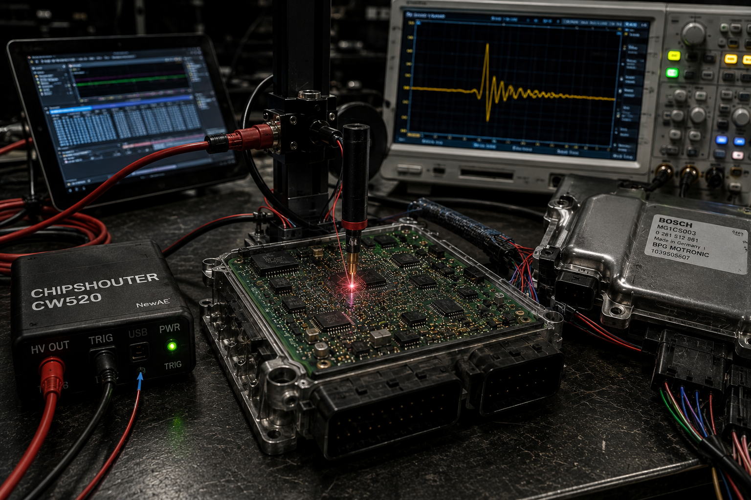
When Software Security Meets Physics: The Engineering Behind Boot Glitch, EMFI and Modern Bosch MG1/MD1 ECU Access
Modern automotive ECU security is no longer a simple battle between a diagnostic tool and a password.
Current-generation Bosch MG1 and MD1 engine control units represent a fundamentally different security environment from many earlier ECUs. The processor itself participates in a protected startup sequence involving boot code, memory permissions, hardware security mechanisms, authentication routines and protected memory regions that cannot simply be accessed because a diagnostic tool knows the correct communication protocol.
This distinction is important because an ECU can be completely functional from the vehicle’s perspective while still being inaccessible from the calibration engineer’s perspective.
The engine starts. Diagnostics work. CAN communication works. Fault codes can be read. Live data can be monitored. The control unit performs every normal vehicle function exactly as designed.
Yet the same ECU may refuse the level of Flash or EEPROM access required for calibration development.
For years, the tuning industry approached these problems almost exclusively from the digital side: diagnostic protocols, security access routines, bootloaders, cryptography, seed-key algorithms, memory permissions and processor debug mechanisms.
But there is another way to think about the problem.
A processor may execute digital software, but the processor itself is still a physical object.
And physics does not disappear simply because the software is secure.
This is the fascinating engineering territory occupied by fault injection technologies and workflows commonly described as Boot Glitch.
Magicmotorsport has publicly described supported Flex workflows using the term Boot Glitch – Bench for a number of Bosch MG1 and MD1 control units. The objective is not simply to “hack a password.” At the engineering level, the interesting concept is that a precisely controlled transient physical disturbance can influence the behavior of a processor during an extremely small timing window.
That field is known as fault injection.
A Digital Processor Is Still an Analog Machine Underneath
When engineers discuss ECU security, we normally describe it using software abstractions.
A bootloader authenticates software.
A security module verifies a condition.
A protected routine decides whether memory access is authorized.
Conceptually, we might describe the result as:
Authorized = 0 if verification fails
From the software engineer’s perspective this appears binary and absolute.
The check succeeds or the check fails.
The processor grants access or the processor refuses access.
But that logical decision is ultimately implemented using physical transistors.
A modern automotive microcontroller may contain hundreds of millions or even billions of semiconductor structures. Registers, SRAM cells, Flash interfaces, buses, comparators, clock trees and CPU pipelines all depend on electrical signals reaching valid voltage levels within specific time windows.
A digital “1” is therefore not really the abstract number one.
It is a voltage.
A digital “0” is also a voltage.
A CPU instruction is not purely mathematics. It is a coordinated sequence of voltage transitions propagating through semiconductor structures according to a clock.
Flip-flops require their inputs to become valid before a clock edge. Logic gates require finite propagation time. SRAM must resolve stored states. Internal buses require settling time. Power-distribution networks must maintain sufficient voltage during switching events.
This means that underneath something as simple as:
if (security_check == VALID)
    continue_boot();
else
    deny_access();
there may be millions of analog electrical events occurring inside the processor.
And analog electrical behavior can be disturbed.
That is one of the fundamental ideas behind physical fault injection.
What an Electromagnetic Fault Injection Platform Actually Does
The NewAE CW520 ChipSHOUTER is a laboratory platform designed specifically for Electromagnetic Fault Injection, usually abbreviated as EMFI.
Its underlying principle is surprisingly elegant.
Electrical energy is stored at high voltage and then released extremely quickly through an inductive injection structure. The resulting rapid change in current produces a rapidly changing magnetic field near the target electronics.
The energy stored in a capacitor can be described as:
Where EC represents stored electrical energy, C is capacitance and V is voltage.
The interesting consequence of this equation is the square relationship with voltage.
If capacitance remains constant, doubling the voltage does not merely double the stored energy.
It quadruples it.
The stored energy can then be discharged into an inductive structure.
For an inductor:
Rearranging the expression gives:
This equation reveals one of the most important engineering ideas in the entire system.
A sufficiently large voltage applied across a relatively small inductance can create an extremely large rate of change of current.
And in fault injection, the rate of change is extraordinarily important.
The objective is not simply “lots of current.”
The interesting quantity is how quickly that current changes.
From Changing Current to Changing Magnetic Flux
Current flowing through an inductive structure creates a magnetic field.
For a simplified magnetic circuit, magnetic flux density can be represented approximately as:
Here B is magnetic flux density, μ is magnetic permeability, N is the number of turns, I is current and l represents the effective magnetic path length.
If current changes rapidly, the magnetic field changes rapidly.
That leads directly to Faraday’s law of electromagnetic induction:
A changing magnetic flux can induce voltage in another conductive structure.
The second structure does not need to be a carefully wound coil.
It may be a PCB trace.
It may be a current loop created by a processor package and its PCB connections.
It may be part of an internal power distribution network.
It may be another conductive path within the physical geometry of the target system.
For two magnetically coupled structures, the relationship can be simplified conceptually as:
where M represents mutual inductance.
That simple expression explains an enormous amount about EMFI.
The fault-injection equipment does not need to electrically connect its high-voltage pulse directly to a CPU signal.
Energy can be coupled electromagnetically.
The system is taking advantage of the same fundamental electromagnetic laws used in transformers, inductors, motors, generators and wireless coupling systems, but applying them over an extremely small spatial and temporal scale.
The Generated Pulse and the Injected Pulse Are Not the Same Thing
This is one of the details that separates actual engineering from a simplistic description of a glitch device.
The waveform commanded by the pulse generator is not necessarily the waveform physically produced by the injection tip.
The ChipSHOUTER documentation explicitly discusses this distinction.
The injection tip itself is part of the electrical system. Its inductance, magnetic core properties, saturation behavior, resistance, parasitic capacitance and physical geometry all influence the final waveform.
Therefore we can conceptually write:
This is incredibly important.
If a pulse generator is commanded to produce a particular digital pattern, the magnetic pulse reaching the target may have a different rise time, fall time, width and amplitude.
The probe can saturate.
Energy stored in the magnetic field can influence the falling edge.
Consecutive pulses may interact with the magnetic state left by previous pulses.
A smaller injection tip may produce a completely different effective waveform than a larger injection tip even when the electronic pulse-generator settings are identical.
This is why professional fault-injection equipment includes monitoring capability.
The experiment must be based on what physically happened, not merely what the software requested.
Why Nanoseconds Matter More Than Impressive Voltage Numbers
A high-voltage specification looks impressive on a datasheet, but voltage alone does not explain why fault injection works.
Timing is at least as important.
The ChipSHOUTER programmable pulse architecture operates with timing resolution measured in tens of nanoseconds, and its dedicated hardware-trigger architecture exists specifically to reduce the delay between a trigger event and the actual fault-injection pulse.
Why does that matter?
Because the processor itself is operating on an extremely small time scale.
The period of a clock is:
If a processor operates at 300 MHz:
That means individual clock events occur only a few billionths of a second apart.
Even though a complete instruction may travel through multiple pipeline stages and require multiple cycles, the electrical logic inside the processor still operates on nanosecond-scale timing margins.
A simplified synchronous timing condition might look like:
The result of the logic operation must arrive early enough for the receiving register to capture valid information.
Now imagine that a transient electromagnetic event changes propagation behavior by a very small amount represented by Δt.
The relationship may temporarily become:
The logical result might now arrive too late.
A register may capture the wrong value.
A comparison may produce an unexpected result.
A memory transaction may not behave exactly as intended.
The processor has not necessarily been permanently damaged.
Its firmware has not necessarily been modified.
For one extremely small period of time, the physical implementation of the digital machine failed to produce the result predicted by its architectural model.
That is precisely what makes transient fault injection so fascinating.
The Objective Is Not to Crash the Processor
A common misunderstanding is that glitching means hitting the processor with enough energy to make it unstable.
That would actually be a poor result.
If the controller simply resets every time a pulse is applied, very little useful information has been gained.
If memory is randomly corrupted, the result is also of limited value.
If communication completely disappears, the experiment has probably moved far outside the useful operating region.
At very low injected energy:
At excessive disturbance:
The useful area lies somewhere between these extremes.
The engineering challenge is to create a disturbance large enough to influence a relevant internal event but small enough that the processor continues executing afterward.
This turns fault injection into an optimization problem rather than a brute-force energy problem.
Fault Injection Is a Multidimensional Search Problem
A useful conceptual model for fault injection success is:
The variables represent different physical and temporal properties of the experiment.
The x, y and z variables represent physical location.
The variable t represents timing relative to the processor operation of interest.
A represents pulse amplitude.
w represents pulse width.
θ can represent probe orientation.
And state represents the internal execution state of the target.
This immediately demonstrates why repeatable fault injection is difficult.
The correct amplitude at the wrong time may produce absolutely nothing.
The correct timing at the wrong location may also produce nothing.
The correct location and timing with too much energy may simply reset the controller.
The correct physical parameters during the wrong phase of the boot process may produce no observable result whatsoever.
A successful system must therefore control multiple independent variables with high repeatability.
This is not very different conceptually from calibration work itself.
A calibration engineer rarely deals with one independent variable. Boost pressure changes mass airflow. Mass airflow changes torque. Torque changes cylinder pressure. Cylinder pressure changes knock sensitivity and thermal load.
Both disciplines require understanding a system rather than looking at a single number.
Physical Position Matters Because the Processor Is Not Uniform
A microcontroller package may appear from the outside to be one black rectangular component.
Internally it is anything but uniform.
The silicon contains different functional regions.
CPU cores occupy particular locations. SRAM occupies other locations. Flash interfaces, bus matrices, clock-generation systems, security peripherals, power-management circuits and communication peripherals occupy still other regions.
The injection field is also spatially dependent.
Electromagnetic coupling changes with distance.
Probe orientation changes coupling.
Injection-tip geometry changes field concentration.
The location of return-current paths on the PCB changes the effective loop area susceptible to electromagnetic induction.
This makes spatial position part of the experimental search.
We can represent probe position as:
And a simplified success function as:
Add amplitude and pulse width:
Now what initially sounded like a simple “glitch trick” has become a multidimensional optimization problem involving position, timing and electrical energy.
That is exactly what it is.
Why Probe Geometry Changes the Result
Injection tips are not interchangeable pieces of metal.
Their dimensions affect the electromagnetic behavior of the system.
Changing the magnetic core geometry changes inductance.
Changing inductance changes current rise behavior.
Changing the physical field geometry changes spatial resolution.
Changing the magnetic material changes saturation characteristics.
This creates an engineering compromise.
A physically larger injection structure may couple energy into a broader region of the target.
A smaller structure may provide improved spatial selectivity.
But changing tip dimensions also changes the electrical load presented to the pulse-generation circuit.
This is one reason the actual inserted pulse must be measured rather than assumed.
The injection tip is not merely an accessory attached after the pulse-generation system.
It is an integral part of the pulse-generation system.
Trigger Jitter Can Determine Whether an Experiment Is Repeatable
Suppose the internal processor event of interest exists only for a tiny timing window.
The injection pulse must arrive within that window repeatedly.
No trigger system is perfectly deterministic.
Every part of the chain adds uncertainty.
A simplified model can be written as:
The external trigger contributes uncertainty.
The pulse-generation hardware contributes uncertainty.
The target itself contributes uncertainty.
The target oscillator may not begin at exactly the same phase during every reset.
Boot execution may contain asynchronous events.
Communication peripherals may influence timing.
Interrupts or hardware startup conditions may introduce additional variation.
This is why trigger architecture matters so much.
A professional fault-injection platform is not simply a capacitor connected to a switch.
It is a measurement and synchronization system.
Boot Glitch Is Best Understood as a Temporary State Manipulation
It is important not to oversimplify what Magicmotorsport or another professional tool developer is doing internally.
The exact ECU-specific implementation is proprietary and can vary considerably between processors, software generations and ECU families.
However, the general engineering principle can be understood without knowing proprietary parameters.
The fault injection event does not need to replace the entire ECU communication system.
It only needs to create the required processor state.
Normal boot can conceptually be represented as:
A successful fault-assisted sequence might instead be represented conceptually as:
This distinction is extremely important.
The electromagnetic event might exist for only a tiny fraction of the entire programming procedure.
Once the required state has been reached, the rest of the communication can proceed digitally.
The memory transfer is digital.
The checksum calculation is digital.
Flash programming is digital.
But the event that made the required access state possible may have been fundamentally analog.
This is where hardware security research becomes so interesting.
The boundary between software and physics disappears.
Why Bosch MG1 and MD1 Represent a New Generation of Calibration Engineering
Bosch MG1 gasoline and MD1 diesel ECUs represented an important technological transition in automotive engine management.
Many variants use sophisticated multicore processors from the Infineon AURIX family together with considerably more advanced security and memory-management architecture than older ECU generations.
This development is perfectly logical from an OEM perspective.
A modern ECU is not simply controlling injectors and ignition coils.
It communicates with gateways, transmissions, stability systems, immobilizer architectures, hybrid systems, driver-assistance networks and many other vehicle modules.
Software integrity is therefore increasingly important.
But the same security mechanisms that protect production vehicles also create new challenges for legitimate calibration development, motorsport engineering, repair research and authorized ECU analysis.
Traditional ECU tools could often gain access primarily through protocol knowledge.
Modern systems increasingly combine software security with hardware-backed security.
That changes the research question.
Instead of asking only:
Can we mathematically defeat the authentication system?
the engineer may also ask:
Can the physical processor be caused to execute one security-relevant event differently while the rest of the system remains operational?
Those are completely different disciplines.
The first problem can often be investigated primarily with software.
The second may require embedded programming, semiconductor behavior, signal integrity, electromagnetics, measurement equipment, automation and statistics simultaneously.
Unlocking an ECU and Tuning an ECU Are Two Completely Different Skills
This distinction is often missed.
Obtaining memory access does not mean that a good calibration automatically follows.
An ECU unlock gives the engineer access to data.
Calibration engineering determines what should be done with that data.
Modern MG1 and MD1 files can contain an enormous number of interconnected calibration tables, constants, axes, physical models and diagnostic thresholds.
The engine-control strategy is generally model based.
The ECU does not simply have one table that says “make 400 horsepower.”
Torque request, airflow, cylinder filling, boost pressure, ignition, fuel, thermal protection and transmission communication are mathematically connected.
A simplified gasoline torque structure can be represented as:
This is the formula that was appearing incorrectly in the previous WordPress version. Here it is pure HTML, so WordPress will display the subscripts directly without requiring MathJax.
Driver demand creates a requested torque.
The torque model determines the required cylinder filling.
Cylinder filling creates an airflow requirement.
The airflow requirement influences boost request.
Boost must then be produced by a physical compressor while the ECU simultaneously manages ignition timing, lambda, exhaust temperature, knock control and component protection.
This means that calibration changes cannot be treated independently.
Changing torque request without correcting the model around it can create inconsistencies.
Changing boost limits without understanding the airflow model can create intervention.
Changing one torque limiter without understanding another may simply move the restriction elsewhere.
This is why modern calibration engineering is a system problem rather than a map-editing problem.
The Turbocharger Still Obeys Thermodynamics No Matter What the Calibration Requests
A calibration may request more boost, but software cannot negotiate with thermodynamics.
The compressor pressure ratio is approximately:
As compressor pressure ratio increases, compressor work increases.
Compressor discharge temperature also rises.
An approximation of compressor outlet temperature is:
Here ηc represents compressor efficiency.
This equation helps explain why “just add more boost” is not an engineering strategy.
Higher pressure ratio produces additional compressor work and additional temperature.
Higher compressor outlet temperature increases charge-air temperature.
Higher charge temperature affects knock margin.
The operating point also moves across the compressor map toward different efficiency islands and potentially toward turbocharger speed limits.
The calibration therefore needs to respect the physical operating envelope of the hardware.
Gasoline MG1 Calibration Is a Balance Between Torque, Airflow, Ignition and Temperature
On a turbocharged gasoline application, increasing torque demand can eventually affect almost every major engine-control subsystem.
More requested torque may require additional cylinder filling.
Additional filling may require additional compressor pressure ratio.
Additional pressure ratio raises compressor work.
Greater cylinder charge raises combustion pressure.
Higher pressure and temperature can reduce knock margin.
The ignition strategy must remain compatible with fuel octane and charge temperature.
Lambda may need to move according to combustion and component-protection requirements.
Exhaust gas temperature becomes important for the turbine, catalyst and other exhaust components.
The torque reported to the transmission must also remain coherent with what the engine is actually producing.
This is why a good MG1 calibration cannot be judged simply by maximum boost pressure.
A calibration producing slightly less boost while operating at better compressor efficiency and better ignition efficiency can sometimes produce a better result than a calibration that simply forces the highest possible manifold pressure.
MD1 Diesel Calibration Has Its Own Completely Different Mathematical Problem
Diesel calibration uses many of the same engineering principles but the control variables and physical constraints differ.
Torque request interacts strongly with fuel quantity.
Fuel quantity interacts with available air mass.
Available air mass interacts with boost pressure and turbocharger operation.
Rail pressure influences injection rate and atomization.
Injection timing affects combustion pressure, thermal efficiency and exhaust temperature.
Lambda and smoke limitation constrain the relationship between air and fuel.
The turbine must produce enough compressor power without exceeding thermal or speed limits.
This creates another interconnected system:
Where SOI represents Start of Injection.
The important symbol here is not only the arrow.
It is the two-way relationship.
Modern control systems constantly estimate and correct these variables relative to one another.
For that reason, modifying a modern MD1 calibration by treating every table as an isolated limiter can produce a vehicle that technically makes more power while behaving poorly in transient conditions.
A strong calibration should remain coherent during spool, part load, gear changes, temperature transitions and full-load operation rather than existing only as one impressive dyno number.
Access Is Only the Beginning of the Calibration Process
Technologies such as professional Boot Glitch workflows are therefore extremely important, but they solve only one part of the problem.
They solve access.
Once a complete and valid original file can be obtained, the real calibration work begins.
The software version must be identified.
The engine and hardware configuration must be understood.
The torque structure must be analyzed.
The required power level must be realistic for the available hardware.
The available fuel must be considered.
And where possible, real operating data should be used to verify the result.
Custom Bosch MG1 and MD1 Calibration Through Eagle Tuning
At Eagle Tuning, we provide custom calibration development for supported Bosch MG1 and MD1 engine control units through our professional file-service platform.
Files can be submitted directly through:
Our objective is not simply to apply a universal percentage increase to a collection of maps.
A calibration can be developed according to the specific ECU software version, engine configuration, installed hardware, fuel type, requested power level and available datalogs.
This distinction becomes increasingly important as the sophistication of the ECU increases.
Two cars may use the same general MG1 ECU family and still require different calibration decisions because of different software versions, turbochargers, fuel quality, exhaust configurations, cooling systems or transmission strategies.
Where additional refinement is necessary, calibration revisions can be based on real operating data.
Boost pressure can be compared with target.
Air mass can be evaluated.
Ignition correction can be monitored.
Lambda behavior can be analyzed.
Torque intervention can be identified.
Temperature behavior can be checked.
The purpose of logging is not simply to prove that a vehicle made a particular number.
Logging allows the calibration engineer to observe how the control system reached that number.
That difference matters enormously.
Modern ECU Calibration Is Becoming a Multidisciplinary Engineering Field
The evolution of ECU access tells an interesting story about the direction of the tuning industry.
First came simple socketed memories.
Then diagnostic flashing.
Then increasingly sophisticated Bench and Boot methods.
Now some control units require techniques originating from hardware-security laboratories and semiconductor research.
At the same time, the calibration strategies inside the ECU have become dramatically more sophisticated.
The industry is therefore moving in two directions simultaneously.
Getting the file has become more technically demanding.
Understanding the file has also become more technically demanding.
Knowing only calibration maps is no longer enough to understand the entire process.
Knowing only communication protocols is no longer enough.
Knowing only electronics is no longer enough.
A modern ECU engineer can encounter embedded programming, CAN communication, microcontroller architecture, semiconductor behavior, signal integrity, electromagnetics, thermodynamics, combustion, control theory and statistical analysis during what the customer may simply describe as “tuning the ECU.”
The Most Interesting Part of Boot Glitch Is the Boundary Between Two Worlds
There is something particularly elegant about electromagnetic fault injection when viewed from an engineering perspective.
On one side of the experiment are equations developed from classical electromagnetic theory.
Capacitance.
Inductance.
Magnetic flux.
Faraday’s law.
Mutual inductance.
These principles existed long before the automotive microcontroller.
On the other side is one of the most sophisticated pieces of electronics in the vehicle: a multicore processor executing millions of security-sensitive operations while managing a modern engine in real time.
Between these two worlds exists a transient electromagnetic pulse lasting an extraordinarily short amount of time.
The pulse does not understand software.
It does not understand encryption.
It does not understand a bootloader.
It only follows electromagnetic physics.
But the secure processor also ultimately depends on electromagnetic physics.
Its security decision must still be represented by charge stored in transistors.
Its instructions must still propagate as electrical signals.
Its registers must still obey timing requirements.
Its internal buses must still settle before clock boundaries.
This is why physical fault injection represents such an unusual intersection of disciplines.
A problem that appears to exist entirely in software can sometimes be influenced at the level underneath software itself.
It Is Not Magic — It Is Engineering at the Nanosecond Level
Professional Boot Glitch technology can look almost unbelievable when viewed only from the outside.
A heavily protected ECU is connected to specialized equipment.
A process runs.
Afterward, a control unit that previously resisted conventional access can enter a state in which normal memory operations become possible.
Without understanding the physics, that can easily look like a mysterious software exploit.
But the deeper explanation is considerably more interesting.
The system combines energy storage, inductive discharge, electromagnetic coupling, semiconductor timing, processor architecture, synchronization and carefully controlled experimentation.
The final Flash read may be software.
The calibration that follows may be software.
The checksum may be mathematics.
But the event that made the transition possible can occur at the level where digital logic becomes analog electronics.
A capacitor stores energy according to:
An inductor responds according to:
A changing magnetic field creates induced voltage according to electromagnetic laws.
The processor operates according to timing constraints measured in nanoseconds.
And somewhere between those equations lies the small window in which physics and software security meet.
That is what makes modern Boot Glitch technology so fascinating.
It is not magic.
It is electrical engineering, semiconductor physics, embedded security and calibration engineering meeting at exactly the same nanosecond.